Perhaps you have heard the term circuit bending and have wondered what it is. The purpose of this article is to explain this black art, both by the generally accepted definition and by how my own experience with it has evolved over 20 years to become more of a hybrid practice. The lines between circuit bending, hacking, and modding can be blurry. I have seen spirited discussions online about what circuit bending is and isn’t, and certainly, there are purists in the mix.
MY BACKGROUND
I have a background in experimental electronic music dating back to 1975 when I took an electronic music course at Northern Illinois University. I discovered circuit bending in February 2004 in the course of a Google search “DIY electronic musical instruments”. I had been interested in creating instruments that would respond to human gestures, but I soon realized I’d have to learn electronics.
I was very familiar with synthesizers and effects, but never had a desire to understand what was going on under the hood. That seemed too daunting at the time, and that is what inspired me to go the DIY route. I wanted to explore creating sound electronically without having to know anything about electronics, and when I stumbled upon an interview with Reed Ghazala, the “Father of Circuit Bending”, a light bulb went off in my head and I began practicing it immediately.
I asked my girlfriend (now my wife, Mona Jean Cedar) if she had any battery-powered toys that made sound, which she did. I walked down to the local Radio Shack and bought test leads with alligator clips and a few electronic components. When I returned home, the journey began. By November of that year, I’d built 11 purely circuit bent instruments. With Mona, I founded “The Highland Park Thursday Evening Circuit Bending Marching Band and Ladies Auxiliary”, and we marched in our very first parade, the Pasadena (CA) DooDah Parade on November 21, 2004.
Later that day, a house fire destroyed all 11 instruments, and we were displaced from our home until February 2006 when reconstruction was completed. An anecdote that is entertaining, now that almost 20 years have passed, is that when the firefighters allowed us to look in the house to see the damage, they told us they heard strange sounds emanating from under the rubble. It was the circuit bent instruments we’d marched in the parade with earlier that day, with batteries still in them. I describe it as one of the most fun days of my life morphing into one of the least fun days of my life. Here we are in the NELA 2023 Holiday Parade (Northeast LA):

HPTEGSCBMBLA/2023 NELA
THE BEGINNING
My complete inexperience with the innards of electronic sonic devices meant I was going to start practicing circuit bending in the purest, most elementary sense. For me this meant going to thrift stores and purchasing toys, bringing them home, opening them up to expose their circuit boards, and shorting various points on the boards with test leads, hopefully altering the sounds the toy made or finding new sounds.
Initially, my personal, rigid practice of circuit bending was to only add switches that would connect two points on a circuit that created an interesting effect when short-circuited with test leads, and not adding any electronic components. I soon realized that most circuit benders were adding potentiometers to these devices, most often to control the pitch continuously, from very low to very high. It did not take long before I discovered that adding components like capacitors and resistors between points of these circuits could produce interesting results. As my skill level increased, I found myself wanting to add more functionality to my instruments, eventually adding IC (integrated circuit) chips and slowly learning to read basic schematic diagrams.
Twenty years in, I have learned not only how to read and create schematics (using software), but I write code for microcontrollers, which I embed in my instruments. I have designed hardware that will allow projected video to actually play my circuit bent instruments in sync with the video. I use sensors such as light-dependent resistors to control pitch by exposing them to light and blocking the light with the hand (a common practice in circuit bending, one which I do not claim to have invented). I also use infrared rangefinders to control the volume of my instruments. I have created instruments that communicate with each other.
That “light bulb” that went off in my head led to a whole world of discovery and inspiration which continues to this day, and what I’ve described here just scratches the surface. Visit my YouTube channel, Bent City to view demos of my instruments, videos of live performances, and a short subject documentary.THE
MYSTERY OF CIRCUIT BENDING
Circuit bending is often a mystery. For example, there are incredible soundscapes that can be created by shorting points on an IC chip of some keyboards – you can’t really know why or how without being the engineer who designed the chip, but it doesn’t matter. You poke around, you find something interesting, and make it a feature. You may get sounds that are nothing like the unmodified device. You may circuit bend a classic talking toy from the 70s or 80s, such as Texas Instruments’ Speak & Spell, which has a voice synthesizer chip that will produce all manner of “alien gibberish”. Other devices may produce a variety of sounds simply by touching the circuit board (body contacts).

Speak & Spell
Another behavior you may encounter is completely unpredictable; momentarily shorting two points on a circuit board may produce a harsh, unpleasant sound one time, or the next time it will actually self-compose, creating strange or even comical phrases or patterns – I have actually taken some of these and transcribed them for conventional musical instruments.
Changing the pitch of devices has the same effect as speeding up and slowing down physical tape. When the pitch goes up or down, the sound pattern speeds up and slows down as well. Often, when slowing the pitch down to extreme levels, the device will produce a high-pitched fluttering sound.
The point I’m trying to make is that if one decides to pursue this art, they may find themselves drawn into a whole new world that can spark their own inspiration and imagination. You may find yourself learning about electronics as an outsider, as I did. I used to work alongside electronic engineers, and they were happy to answer any questions I had or offer advice concerning my designs. More than once, I was told that I approached things differently than they did as trained electronics students, and because I was an outsider, I would come up with ideas that would never occur to them.
As with many things in life, if you approach things completely naively, and are not bound by rules or assumptions that you were taught, you are more open, and more likely to experiment and take chances. The beauty of circuit bending, especially in the beginning when you are probably poking around in a $4 thrift store toy, is that if you destroy it, it’s not a heartbreaking loss. The low risk makes it easier to take chances, and you WILL destroy circuits in the process of circuit bending.
GETTING STARTED IN CIRCUIT BENDING
Should you decide to take the plunge and start circuit bending, here are some things to consider. The most important of these is not to open and poke around in a device that connects directly to AC power, for obvious reasons – survival! Work on things that run on batteries!
Another piece of advice I feel strongly about is to avoid circuit bending something that has a great deal of value in its unaltered state, unless its primary value is as a target for circuit bending. If you kill something you treasure, you will suffer great heartbreak. If you kill something you don’t care about in its unbent state, you may feel heartbreak at killing something that may have resulted in a really cool bent instrument, but that is part of the risk of circuit bending. You may kill or reduce the lifetime of a device that you circuit bend. Circuit bending a vintage synthesizer is unlikely to produce great results, and the risk of destroying it or its value are not worth it.
There are also collectibles that may be good candidates for circuit bending, and if you own such a thing you might want to consider leaving it alone and preserving its monetary value. I circuit bent a toy saxophone, the “Sax-A-Boom” years before Jack Black made it famous by playing it in his band, Tenacious D. Now they fetch a pretty penny.
There are many different types of electronic devices that are good targets for circuit bending–battery-powered kids toys, some drum machines, keyboards, etc. You may already own some “bendable” items. You might know someone with kids who’ve outgrown their toys, or you could go to thrift stores.
ESSENTIAL TOOLS AND SUPPLIES
Once you’re ready to dive in, there are things you’re going to need:
- Test leads with alligator clips
- Jewelers screwdrivers
- Soldering Iron
- Solder
- Solder sucker, for removing solder from a joint (desoldering)
- Potentiometers, linear taper. A 6mm (sometimes listed as ¼”) shaft diameter will accommodate most knobs. I keep the following values in stock: 1KΩ, 5KΩ, 10KΩ, 20KΩ, 50KΩ, 100KΩ, 250KΩ, 500KΩ, 1MΩ – “Ω” is the symbol for “ohm”, the measure of resistance.
- ¼ watt resistors – I keep the following values in stock: (100Ω, 220Ω, 330Ω, 470Ω, 680Ω, 1KΩ, 2.2KΩ, 3.3KΩ, 4.7KΩ, 6.8KΩ, 10KΩ, 22KΩ, 33KΩ, 47KΩ, 68KΩ, 100KΩ, 220KΩ, 330KΩ, 470KΩ, 680KΩ, 1MΩ)
- Toggle switches – I almost always use subminiature size. SPST (single pole single throw) is for turning one connection on or off. SPDT (single pole double throw) is commonly used to connect 2 different points to one point. DPDT (double pole double throw) is like 2 SPDT switches combined into 1.
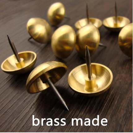
- Brass furniture/upholstery tacks, for body contacts. Other brass parts will work as well.
- ¼” jacks
- 26 AWG stranded wire. I highly recommend getting the full 10-color for color coding purposes. In more complex projects, you can easily lose track of wiring. I usually assign a number to every “bend” (connection between 2 points on a circuit), and then use the typical electronic color coding system when choosing the wire color for a given bend. So, for example, for “bend 4”, I would use yellow wire. This is the system:
Brown = 1
Red = 2
Orange = 3
Yellow = 4
Green = 5
Blue = 6
Violet = 7
Gray = 8
White – 9
Black =0
- Black oxide masonry drill bits, for drilling holes in plastic. I like these because there is no “pull” once you’ve broken through the plastic. That can cause the drill bit to hit the circuit board, damaging or destroying it.
- Knobs (mainly to fit pots 6mm or ¼”)
Down the road, should you get more serious about circuit bending:
- Rotary switches. Used to connect one point in the circuit to other points. A 1-pole, 12-position rotary will connect 1 point in a circuit to up to 12 different points (one for each position)
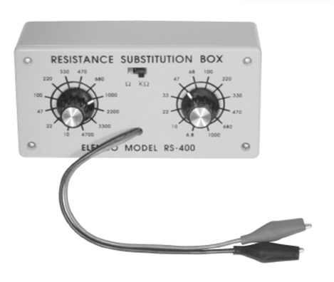
- Resistance substitution box. Connecting the clips to 2 points on the circuit, you can quickly determine which resistor value produces the desired effect.
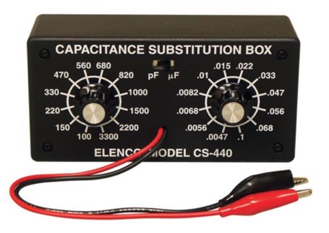
- Capacitance substitution box. Connecting the clips to 2 points on the circuit, you can quickly determine which capacitor value produces the desired effect.
- Digital multimeter. Test for continuity, short circuits, voltage, and more.
- Oscilloscope – not cheap, but a great tool if you want to see what’s going on in circuits “under the hood”. For very serious benders.
MY PROCESS
I won’t go into the greatest detail of my circuit bending process, just the basics to get started. There are many resources online to guide you should you go deeper. I am sharing some of my fundamental practices which you may find useful.
I take a photo of the circuit board that shows all the possible connection points (nodes) clearly. These nodes are any point in the circuit where solder appears. Using Photoshop, I number each point sequentially starting with “1”, and then print out the result. It doesn’t matter which point you start with, the purpose of this numbering is to provide a reference to the actual circuit board without having to mark the board itself. It is a good idea for these numbers to follow some sort of path rather than being randomly scattered. This is a typical example:
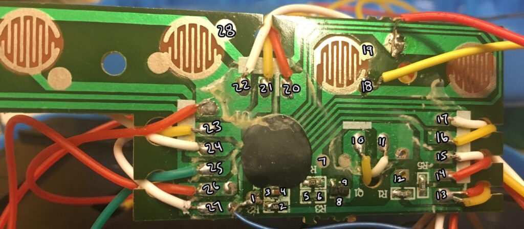
Bentacles (Megcos No_1259 Musical Octopus)
With more complex circuits, I assign a number and draw a path in Photoshop following the circuit board trace (on most circuit boards, it is the lighter green areas) and when it leads to another node, I will “x out” that node; since it is connected by the trace to the other node, there is no need to test it–it would be redundant. Here is an example of this practice:
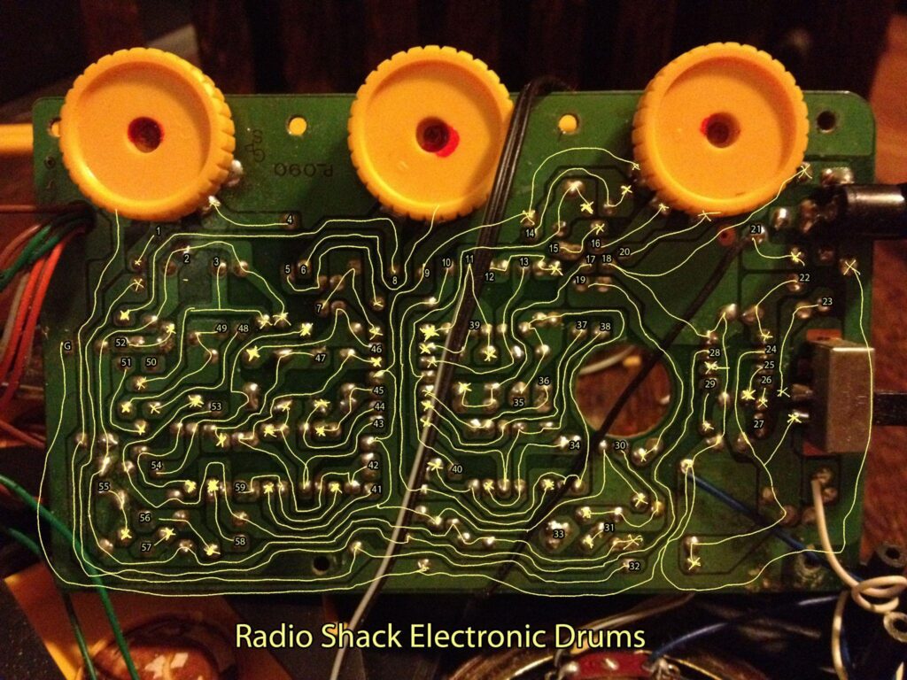
The next step is to start exploring the circuit! Have a printout of the numbered circuit board, pen/pencil, and paper ready to take notes on what you discover. If the device has a power switch, turn it on. One of the first things I do is moisten my fingertips and touch around the circuit board with both hands. Sometimes this will produce tones if touching 2 points causes feedback. You can more precisely locate the points creating sound by holding a jeweler’s screwdriver in each hand. Let’s say touching point 3 to point 19 creates an interesting sound by touching. I would make a note that reads something like “3-19 body contact – high-pitched squeal”. You can push 2 brass upholstery tacks into the plastic body of the device while heating them with a soldering iron, melting the plastic so they slide in. Then, on the inside, solder a wire to the points of each tack. Solder the other end of one wire to point 3 and the other to point 19. You will recreate the “squeal” by touching the tack heads. These are called “body contacts”.
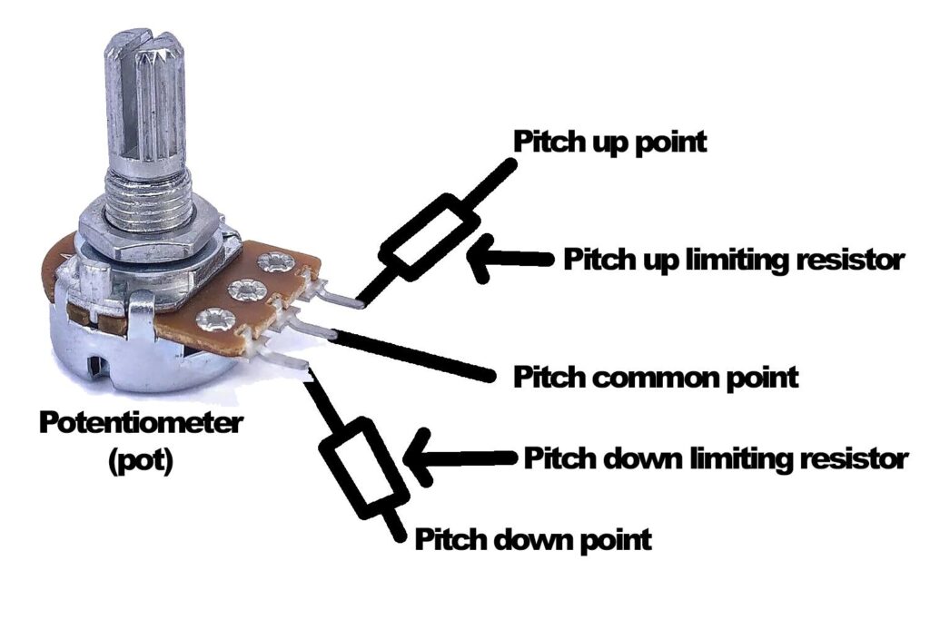
I then repeat this process while the device is making sound, to see what effect touching the board has on the sounds it makes. On many circuits, this will lead to the discovery of pitch change. Typically, there will be 3 points related to this function–connecting one point to another will raise the pitch, and connecting one of those points to another will lower it, so one of the 3 points is the common point, one of the remaining points will be pitch up and the other pitch-down. The common point will be wired to the center lug of a potentiometer (pot) via an on/off toggle switch to enable or disable variable pitch. Pitch up and pitch down will be connected to the outer lugs of the pot. Turning the pot will vary the pitch between high and low.
A note about this type of pitch control–the reason it is effective to use fingertips to find pitch points is that connecting those points with wire (a dead short), will often lower or raise the pitch beyond your hearing range, and often this will crash the device as well. For this reason, resistors are often required between the pot and the pitch up/down points to limit the range of the pitch control.
I like to insert a switch between the common point and the center lug of the pot for a couple of reasons. First, I like to be able to switch between normal and variable pitch. Second, often the device will not activate if the pitch is set too far away from normal.
Another method of changing the pitch is by determining the location of a resistor that sets the pitch, removing one end of it, connecting it to a switch that will either reconnect it to the point from which it was removed or connect it to a pot which will make the pitch variable.
Potentiometer
After exploring the circuit with your fingers, you can proceed to exploring with test leads. A test lead with alligator clips at the ends holding jeweler’s screwdrivers works well. Referring to the printout of the numbered circuit board photo, I will typically test point 1 connected to point 2, point 3, point 4 etc. until all connections have been explored. Then point 2 to point 3, etc. until all combinations have been tested, making notes of which combinations produce interesting results. Some devices will produce amazing results, others may produce very little. Here are photos of the numbered circuit board and a page of my bending notes for the incredible Coleco Talking Teacher from 1985:
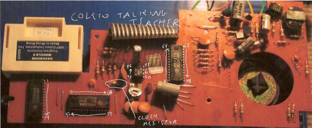
Talking Teacher circuit board
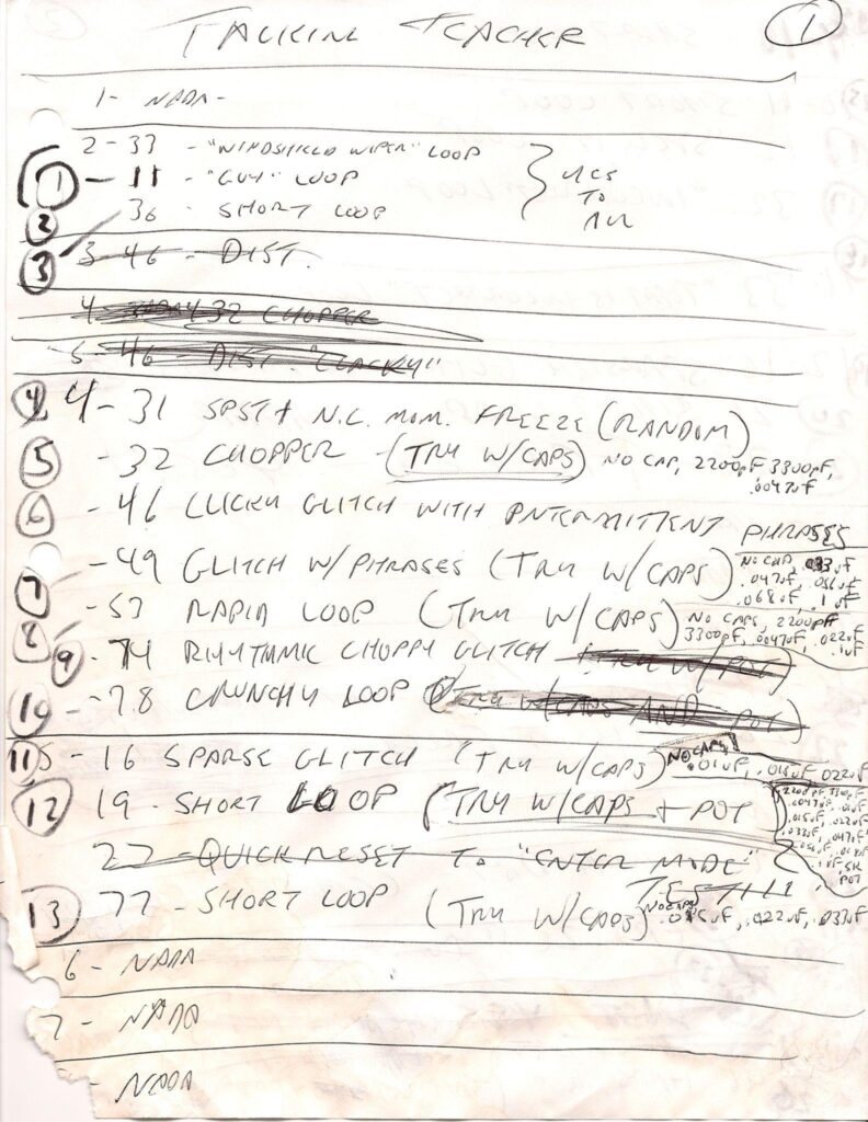
Squawking Screecher Bending notes
The page of bending notes shows my descriptions of the effects of connecting the following pairs of points: 2-33, 2-11, 2-36, 4-31, 4-32, 4-46, 4-49, 4-53, 4-74, 4-78, 5-16, 5-19, and 5-77.
If you want to activate any of these points, you would drill a hole in the plastic case, insert a toggle switch, and bolt it in place. You would then solder a wire to each of the points on the circuit board and solder each wire to one lug of the switch. When you flip the switch on, you activate the bend.
On some devices, momentarily connecting two points will result in totally unpredictable results – a glitch, a harsh noise, or the device will start randomly composing. In such cases, you would install a normally open (N.O.) momentary push button switch, which only connects when pressed.
CONCLUSIONS
I describe circuit bending as a black art because often it is taking an action and getting a result that is astonishing but inexplicable. There are many potential targets for circuit bending out there, and a wide range of behaviors resulting from applying the techniques of circuit bending. In addition to what is described above, circuit bending can result in distortion, fluttering of pitch, robotic voices that randomly glitch and spout often unintelligible gibberish, drones, evolving soundscapes, and many other aberrations.
A final thought–and this is what attracted me to circuit bending–ANYONE can do it. It is low risk, in that if you destroy a toy you paid $3 for at a thrift store, you won’t be devastated. You do not need to know anything about electronics, but if you stick with it long enough, you will begin to understand more as you go along. I knew nothing about electronics when I began–now I can read schematics, design my own circuits, and I even learned to write code for Arduino-based microcontrollers which I embed in my instruments. It’s been an amazing journey!
For more information about my complete circuit bending experience, please visit my website: www.bentcity.com
ABOUT THE AUTHOR
Jeff Boynton is a DIY artist/musician living in Los Angeles. He studied Theory and Composition, and Electronic Music at Northern Illinois University from 1974-77. He joined I.R.S. Records recording artist Wazmo Nariz in 1978 as keyboardist, which toured the United States and Europe both as headliner and in support of such groups as The Police, Devo, XTC, and the B-52s. The band was dissolved in 1981. In 1993, Jeff composed music for “Super Illusion”, which toured 11 cities throughout Japan with the Bolshoi Circus from Moscow, Russia.
In 2004, he began to explore “circuit bending”, which is the art of opening up electronic sound-generating devices and intentionally short-circuiting points on their circuit boards in search of interesting and perhaps never-before-heard sounds. Jeff has developed a prestigious international reputation in this field. The sounds generated by his devices have been used in compositions and live performances, including several collaborations with choreographer Rudy Perez. The first of these was “Double Play” (2004) The next was “Double Play Revisited”, performed at the REDCAT Theater in the Walt Disney Concert Hall complex in downtown Los Angeles, as part of the NOW Festival. Jeff currently performs as part of “Circuitry And Poetry” with wife Mona Jean Cedar, a dancer, poet, and sign language interpreter. They performed “Bent Haiku” at the REDCAT Theater in 2007 in which he created a sonic backdrop using his circuit bent instruments over which Ms. Cedar performed original poetry while simultaneously interpreting it with dance and sign language. Jeff performs regularly with his circuit bent instruments, both in a solo capacity and in ensembles.
EXTRAS
Assess your knowledge of essential audio concepts using our growing catalog of online Quizzes.
Explore more content available to Subscribers, Academic, and Pro Members on the Member Resources page.
Not a Member yet? Check the Member Benefits page for details. There are FREE, paid, and educational options.


